Starting A Gamepad Blog On WordPress? Don’t Forget These HostGator Coupons
Plenty of controller blogs start the same way. You fix your own stick drift, write up what worked, and realize you…

Everyone says Hall effekt sticks are better but I don't understand how Joystick a magnet can tell where the stick is. Can someone explain how it works in simple words? Also what is the difference between a Hall sensor and a Hall potentiometer, I see both words in shops.
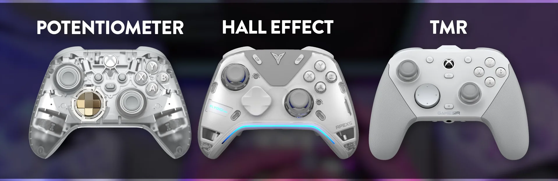
A small magnet moves with the stick and a sensor under it measures the magnetic field. Each stick position gives a different reading, which the controller turns into stick values. Nothing rubs, so nothing wears. Hall potentiometer is shop wording for a Hall effect sensor shaped to replace a potentiometer.

Happy to. Start with what a normal stick does. A potentiometer is a strip of resistive material with a small contact sliding along it. Move the stick and the contact moves, changing the voltage the controller reads. It works well, but the contact rubs, and rubbing wears.
A Hall effect stick replaces the rubbing with a magnet. A tiny magnet is fixed to the bottom of the stick's shaft, and a Hall sensor sits under it on the circuit board. The Hall effect, discovered in 1879, says that when a magnetic field passes through a conductor carrying a current, a small voltage appears across it, and a stronger field gives a bigger voltage. So as the stick tilts, the magnet moves relative to the sensor, the field through the sensor changes, and the voltage changes with it.
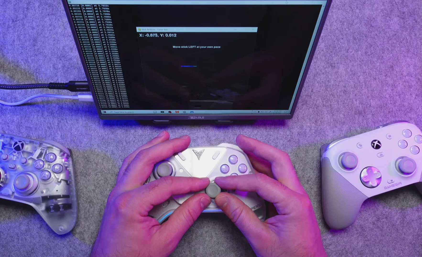
Measure that in two directions and you know where the stick is. The controller's chip reads those values many times a second, applies its calibration, and turns them into the minus one to plus one values our tests show.
Because the magnet and sensor never touch, the classic wear that causes drift does not happen. Calibration and nearby magnets can still shift the reading, which is why magnetic sticks are drift resistant rather than magic.
On the shop wording: Hall potentiometer is not a technical term. Sellers use it for Hall effect modules shaped like a potentiometer so they fit the same spot. Same idea, different label.
Tested on: General explanation for Hall effect, TMR and potentiometer controllers. Sensor principles per manufacturer technical notes from GuliKit and published explainers.
Checked by Chloe Henderson on . How we verify answers
Calibration And Signal Processing Programmer at Gamepad Tester
Arjun writes the maths between a controller and the screen. A raw axis value is noisy, unscaled and centred imperfectly, so his filters handle the parts that decide whether a test is useful: removing sensor noise without hiding a genuine fault, normalising ranges across controllers that report differently, and plotting the result as a clean graph where real drift is visible and jitter is not mistaken for it. On Gamepad Tester he maintains the calibration maths in the deadzone and drift tests, and explains in answers what a given reading does and does not prove.
 Calder WrightFront-End Web Architect And Gamepad API Lead
 Elena RostovaHardware Diagnostics Engineer
 Garrett LindsayHardware Reviewer And Input Performance Specialist
 Venom’s Tech (Abhishek)Peripheral Reviewer And Tech Journalist
 Chloe HendersonHall Effect And Thumbstick Analyst
 Thiago AlvesHardware Repair Educator
 Devon MillerLow Latency And Input Timing Engineer
 Liam DaviesBluetooth And Wireless Test Engineer
Each answer is written by the specialist who owns that part of the hardware, tested on a real controller, and checked by a second team member. How we verify answers
Answers are free general guidance from the Gamepad Tester Team and the community. Opening a controller or replacing a thumbstick module can void your warranty, so check the maker's support or warranty first. Battery and soldering work carries a real risk of damage or injury.
Every test runs in your own browser with the Gamepad API. No sign up, no download, and your controller data never leaves your device.
Plenty of controller blogs start the same way. You fix your own stick drift, write up what worked, and realize you…
If you play games on a PC, whether that means ranked matches every night or a slow campaign on the weekend, you know…
Sony has not announced the PlayStation 6. That is the honest starting point, because almost everything circulating…
The newest replies from players and the Gamepad Tester Team.